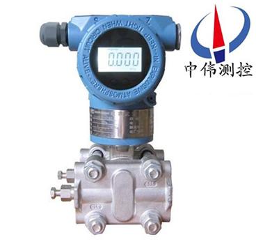
Capacitive Micro Differential Pressure Transmitter
I. Product Overview:
ZW1151DR series capacitive differential pressure transmitter is a new type of transmitter which imports advanced technology and equipment from abroad. The key raw materials, components and components are all imported. The whole machine has been rigorously assembled and tested. The product has the characteristics of advanced design principle, complete varieties and specifications, simple installation and use. Due to the appearance of the full integration of the current domestic Zui for popular, in order to adapt to the continuous improvement and development of domestic automation level.
II. Working Principle:
ZW 151DR series capacitive micro differential pressure transmitter is used to measure the two pressures of the medium into high and low pressure chambers. It acts on the isolation diaphragm on both sides of the delta element (i.e. the sensitive element), and is transmitted to both sides of the measuring diaphragm through the isolator and the filling liquid in the element. A capacitor is formed by measuring the diaphragm and the electrodes on both sides of the insulating sheet. When the pressure on both sides is inconsistent, the displacement of the diaphragm is proportional to the pressure difference, so the capacitance on both sides is different, and the signal is converted into a signal proportional to the pressure through oscillation and demodulation.
3. Application occasions:
ZW 151DR series capacitive differential pressure transmitter is used to measure liquid level, flow rate and pressure of liquid, gas or steam under high working pressure environment, and then convert it into 4-20 mA DC signal output. Intelligent type can communicate with HART hand-operated device, through which setting, monitoring or composing on-site monitoring system with upper computer.
Fourth, main characteristics:
1. Super measurement performance for pressure, differential pressure, liquid level and flow measurement;
2. Digital accuracy: +(-) 0.05%;
3. Stability: 0.25% for 60 months;
4. Range ratio: 100:1;
5. Measurement rate: 0.2S;
6. Miniaturized (2.4kg) stainless steel flange, easy to install;
7. Process connection is compatible with other products to realize measurement.
8. The sensor (technology) with H-alloy sheath has achieved excellent cold and thermal stability.
9. Microdifferential pressure transmitter with 16-bit computer;
10. Standard 4-20mA, with HART-based digital signal, remote control supports upgrading to fieldbus and field control technology.
Technical parameters:
1. Targets: liquids, gases and vapors;
2. Measurement range: 0.25-1.5KPa;
3. Output signal: 4-20mA DC (special for four-wire system); 220V AC power supply, 0-10mA DC output;
4. Power supply: 12-45V DC, generally 24V DC;
5. Load characteristics: related to power supply, with load capacity at a certain power supply voltage; the relationship between load impedance RL and power supply voltage Vs is: RL < 50 (Vs-12);
6. Indicator table: pointer linear indicator 0-100% calibration and LCD liquid crystal display;
7. Explosion-proof grade: a: Exd II BT5 or Exd II CT6; b: intrinsically safe type (Exia II CT6 or Ex IB II CT6);
8. Range and Zero: External continuous adjustable.
6. Installation matters needing attention:
When the differential pressure transmitter and throttle device are used together, when the field pressure is low, the upper limit of differential pressure calculated is micro differential pressure, which puts forward high requirements for the field differential pressure transmitter.
Installation of pressure guide pipe:
1. Differential pressure transmitter changes pressure because of its small range and different installation position. When the slope is 30 degrees, the pressure on the left and left side of 0.2KPa will be generated. In this case, especially when it is used in conjunction with the Anuba flowmeter, attention must be paid to the installation of differential pressure transmitter.
2. Prevent the transmitter from contacting the corrosive or overheated medium under test.
3. Prevent the sediment from depositing in the pressure guide tube.
4. The guide pipe should be as short as possible.
5. The liquid column indenters in the guide tubes on both sides should be balanced.
6. The pressure guide pipe should be installed in the place where the temperature gradient and fluctuation are small and there is no impact and vibration.
In the field measurement, the methods of reducing errors are as follows:
1. The guide pipe should be as short as possible.
2. When measuring liquid vapor, the pressure guide pipe should be connected up to the process pipeline, and its slope should be no less than 1/12.
3. For gas measurement, the pressure guide pipe should be connected downward to the process pipeline with a slope not less than 1/12.
4. High points should be avoided in the layout of liquid pressure guide pipes and low points should be avoided in the layout of gas pressure guide pipes.
5. The same temperature should be maintained for the two pipes.
6. In order to avoid the friction effect, the diameter of the guide pipe should be large enough.
7. There should be no gas in the pressure pipe filled with liquid.
8. When isolating fluid is used, the liquid level of the pressure guide pipes on both sides should be the same.


